Input Devices
Assignment
Measure something: add a sensor to a micro controller board that you have designed and read it.Learning Outcomes
Demonstrate work flows used in circuit board design and fabrication.Implement and interpret programming protocols.
Design Process
Temperature Sensor Board
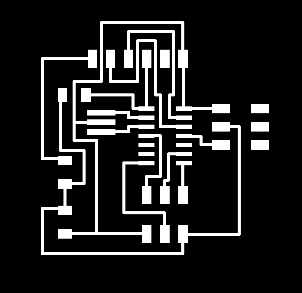
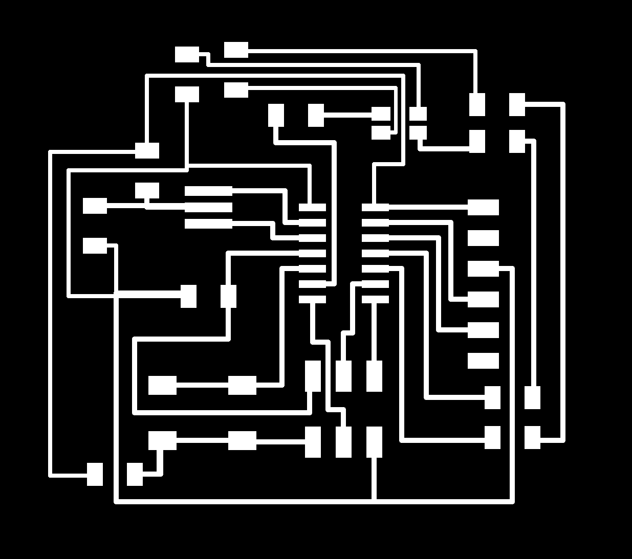
To begin this week I wanted to first start out by using the DHT11 Temperature and Humidity sensor and design a board that I could monitor the temperature with because I needed this component for my final project. To begin I used to skills I learned in Week 6: Electronics Design and drew up a schematic for the board in Eagle. Following Craig Hobern's advice, I did not use auto router and manually drew the routes for the board layout. Below is the final schematic and board layout for the Temperature Sensor Board: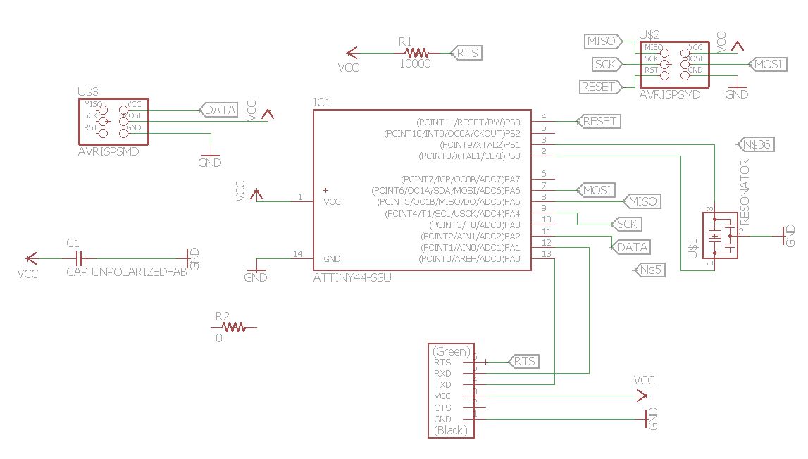
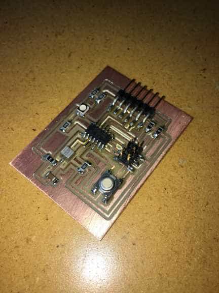
I then was able to stuff the board with its components. Once I plugged the board into the AVR MKII for programming, I immediately got a blinking orange light on it. I tried to program the board to work properly but was unable to since I could not find the right libraries and was unable to upload the code. Another problem was the libraries I was using were fairly big and they took up a lot of storage on the ATtiny44.
RGB LED Board
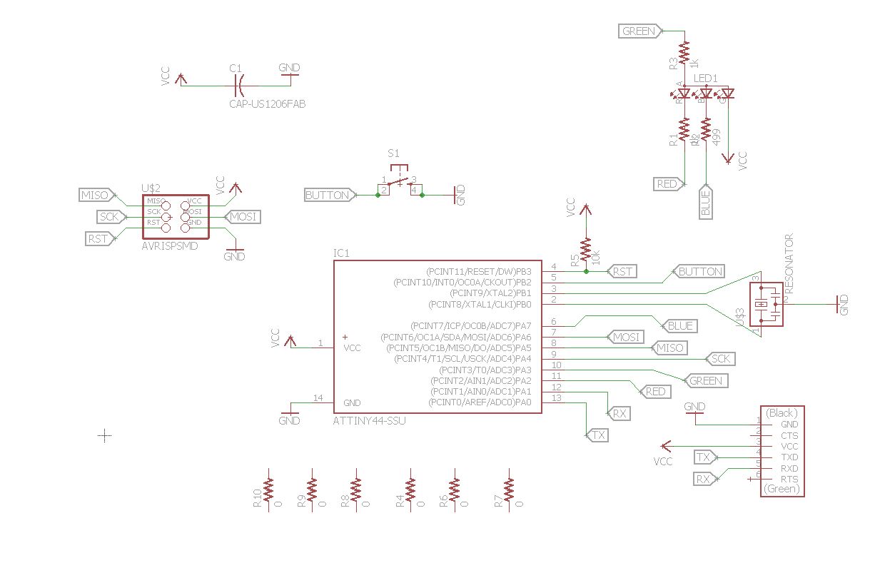
Since I could not get the temperature sensor board working, I decided to move in a different direction and use a board that had better documentation with it. I found Andrew Mao's page that had good documentation on how his board was built and how he programmed his board. Again using the skills from Week 6 I drew up a schematic in Eagle. However, after stuffing the board and trying to program it, nothing would happen to the LED. I went back to the Eagle schematic and realized I had done something really stupid. I didn't put any power supply on the LED itself.
Once I had fixed that problem, I was able to lay out the below schematic. I stuffed the board, adapted and uploaded a simple code from Andrew Mao's page that just controlled the LED to make sure I had power going to it this time. Luckily I did have things laid out properly and the RGB LED worked. The below video shows the LED flashing.
If video is not playing in current browser, please play it here: RGB LED video

Now since this is input week, I now had to program the button on the board to control the LED.
RGB LED Button
Since I now know the LED works, I now had to get the button working to control the LED. I found Liz Schell's page in which she adapted Neil's hello.RGB.45.c code to work with her button and LED. I was able to take her code and change the pin numbers with which my LEDs and button were on. Once it was uploaded I pressed the button on my board and VOILA! The RGB LED lit up and was transitioning colors!If video does not play in current browser, please play it here: RGB LED Button video
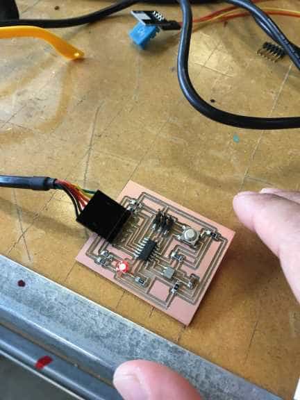
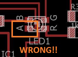
But wait... the green LED is no where to be seen. So what could be the problem? After doing some research and talking with Craig Hobern he suggested that I use a smaller sized resistor. I switched that out and still no luck in getting the green LED to light up. I then took a wire and went straight from ground on the FTDI to each LED pin. The red and blue lit up, but the green still wouldn't light. So I tested an LED by itself with a wire hooked up to the VCC and one hooked up to ground on the FTDI. I then put VCC on what I thought was the anode of the LED and touched the ground wire to each pin. The blue and red pins worked fine, but the green one still wouldn't light. I then switched VCC to what I thought was the green pin and put ground to what I thought was the anode pin and the green LED finally lit up! The layout in Eagle has the green pad and anode pad switched.
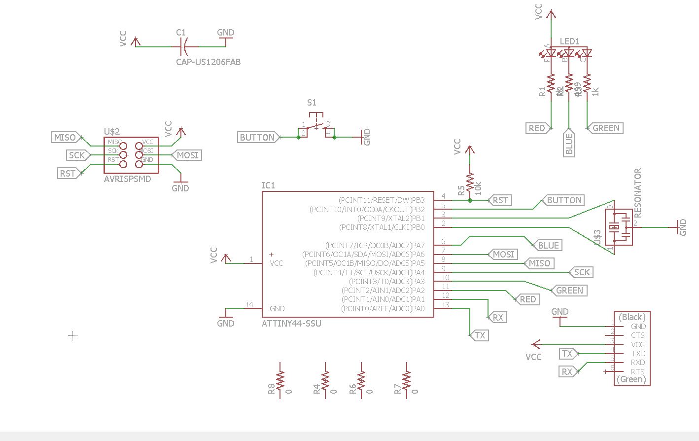
So I went back into Eagle and redid the nets and had to add more zero ohm resistors to jump some traces. I came up with the final schematic and board layout below:
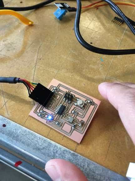
I uploaded the code again and this time it transitioned through all the colors this time! The video is below:
If the video does not play in the current browser, please play it here: Proper RGB LED Button
I then wanted to double check to make sure the button was working properly. I uploaded a simple code that had the red LED stay on and anytime the button was pushed it would turn off. This code uploaded fine and can be seen working as it should below:
If video does not play in current browser, please play it here: Button Test Video
Lessons Learned
1. Don't trust the layouts in Eagle.2. Keep trying and you will succeed.
3. I'm getting fairly good at building boards and also don't expect to build a board to work well the first time.
Project Files
Temperature Sensor Board
Temperature Sensor SchematicTemperature Sensor Trace
Temperature Sensor Outline
RGB LED Board
RGB LED SchematicRGB LED Board Layout
RGB LED Trace
RGB LED Outline
RGB LED Code Files
Test LED Code.cMakefile for Test LED Code
RGB LED Button Code
Button Test Code